Diavolino - Arduino from Hell!
Halloween is coming. We needed a special electronic project. And in Micro Center was spotted an interesting Arduino clone right from the Hell. Because its name is Diavolino which means little Devil.
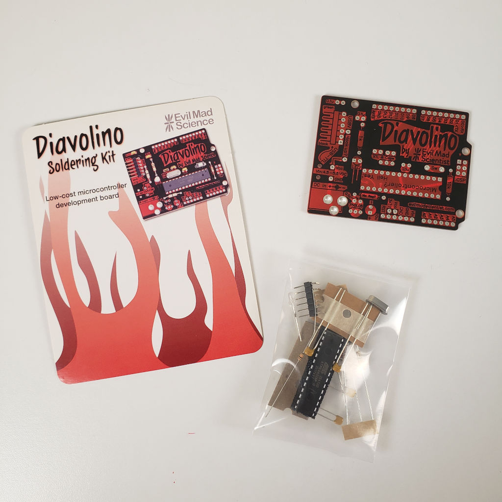
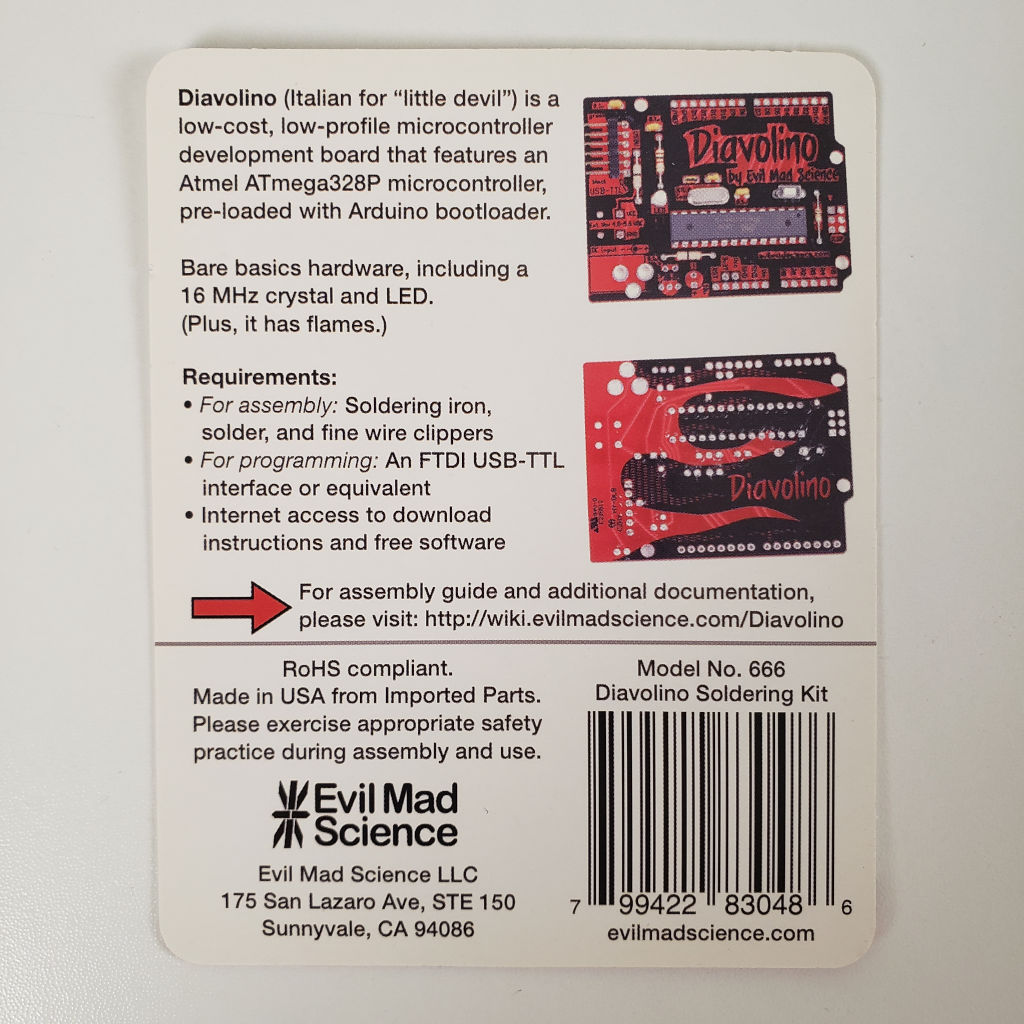
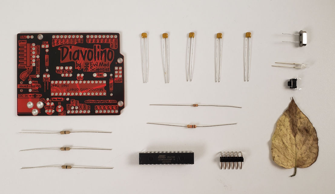
Made in USA by Evil Mad Science LLC. It's claimed to be a cheap Arduino compatible development board. I'm sure that Chinese boards would argue who is cheaper. Nevertheless, the board looks cool, minimum components, easy to use, overall it is worth to try. You should keep in mind that you can't just plug this board to USB like any normal Arduino. You have to have ab USB TTL interface. Also, I would recommend having a 28-Pin DIP IC Socket Adaptor rather than soldering the microcontroller directly into the board. Also I added pin headers. All these parts I added from our storage.
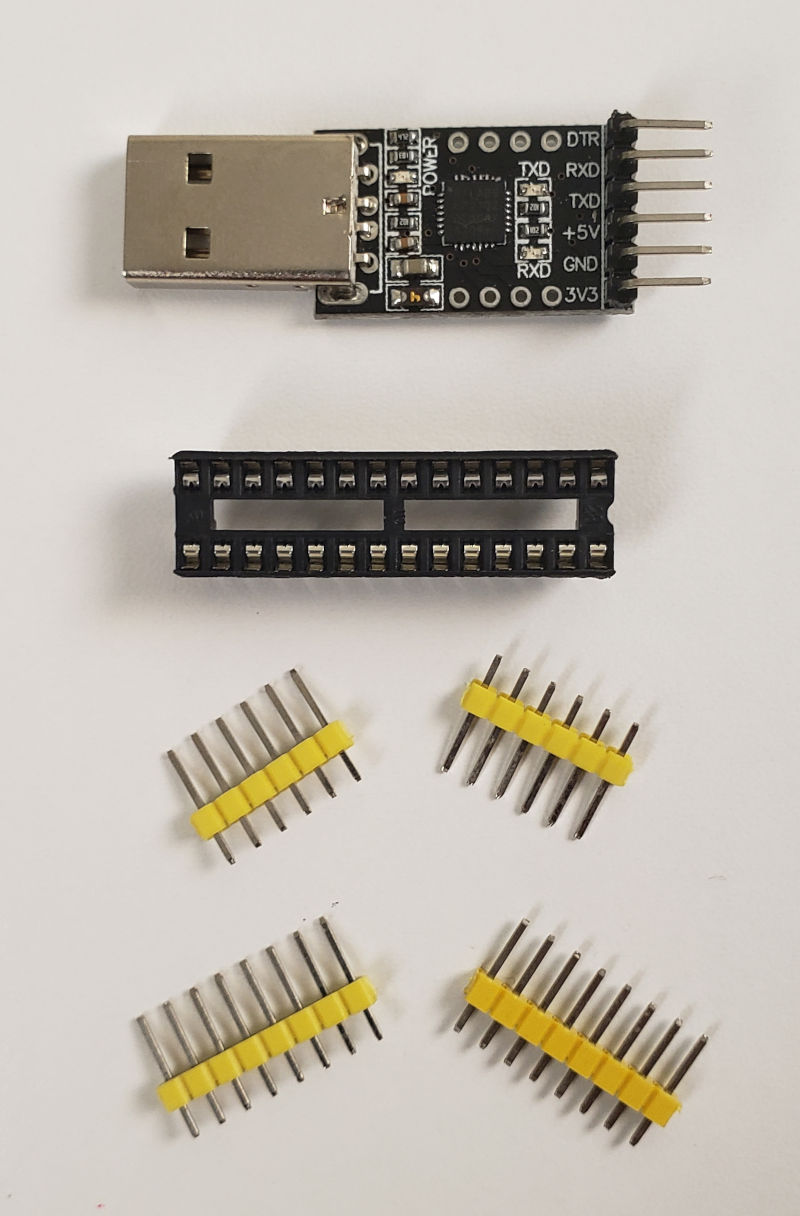
The first step is soldering a 28-Pin DIP IC Socket Adaptor.
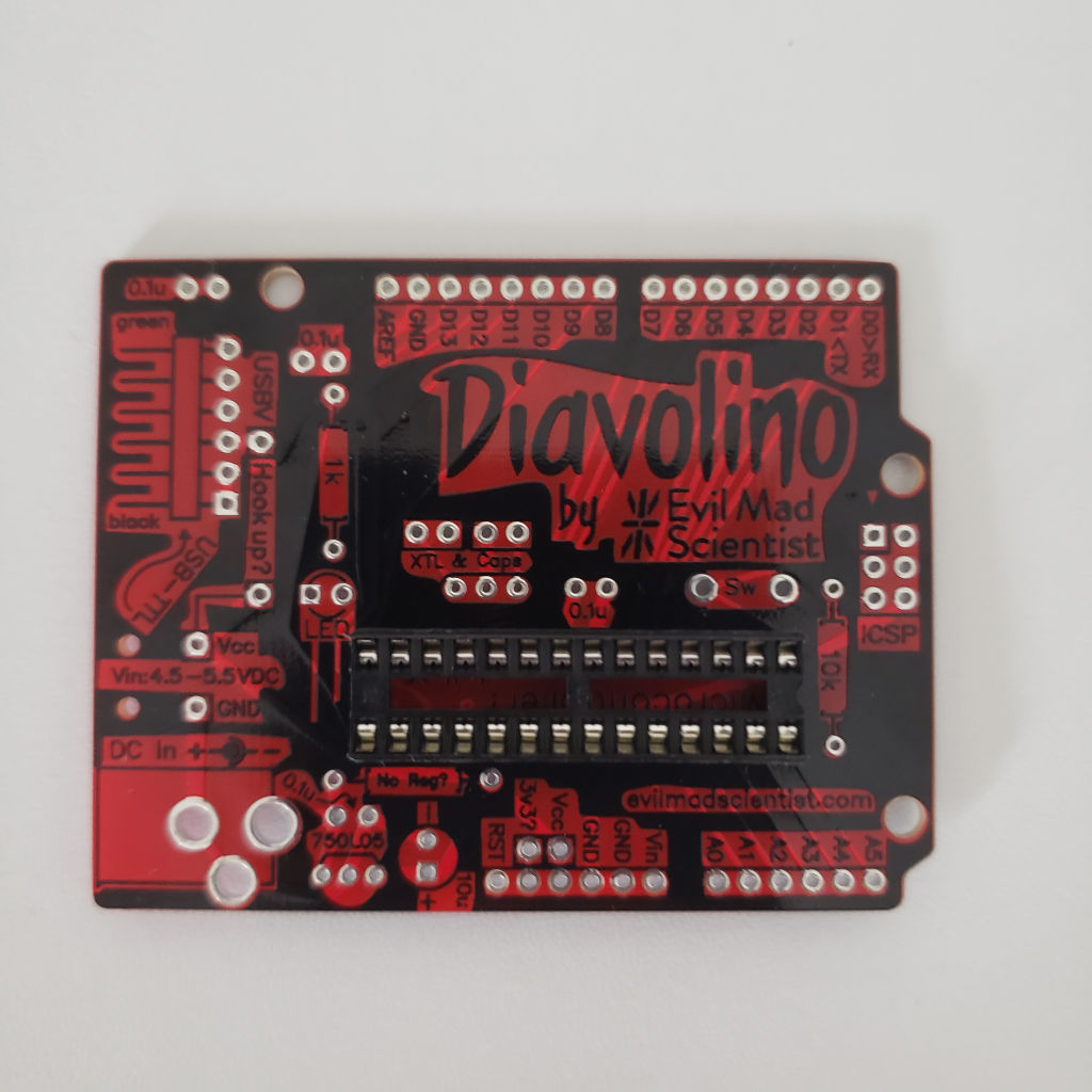
Then we can solder the resistors. The 1K resistor is a big one, and the 10K resistor is small.
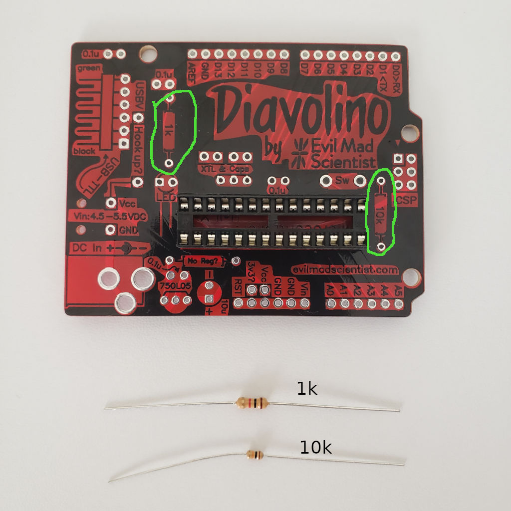
Next, 18 pf capacitors. There are 2 of them in the kit.
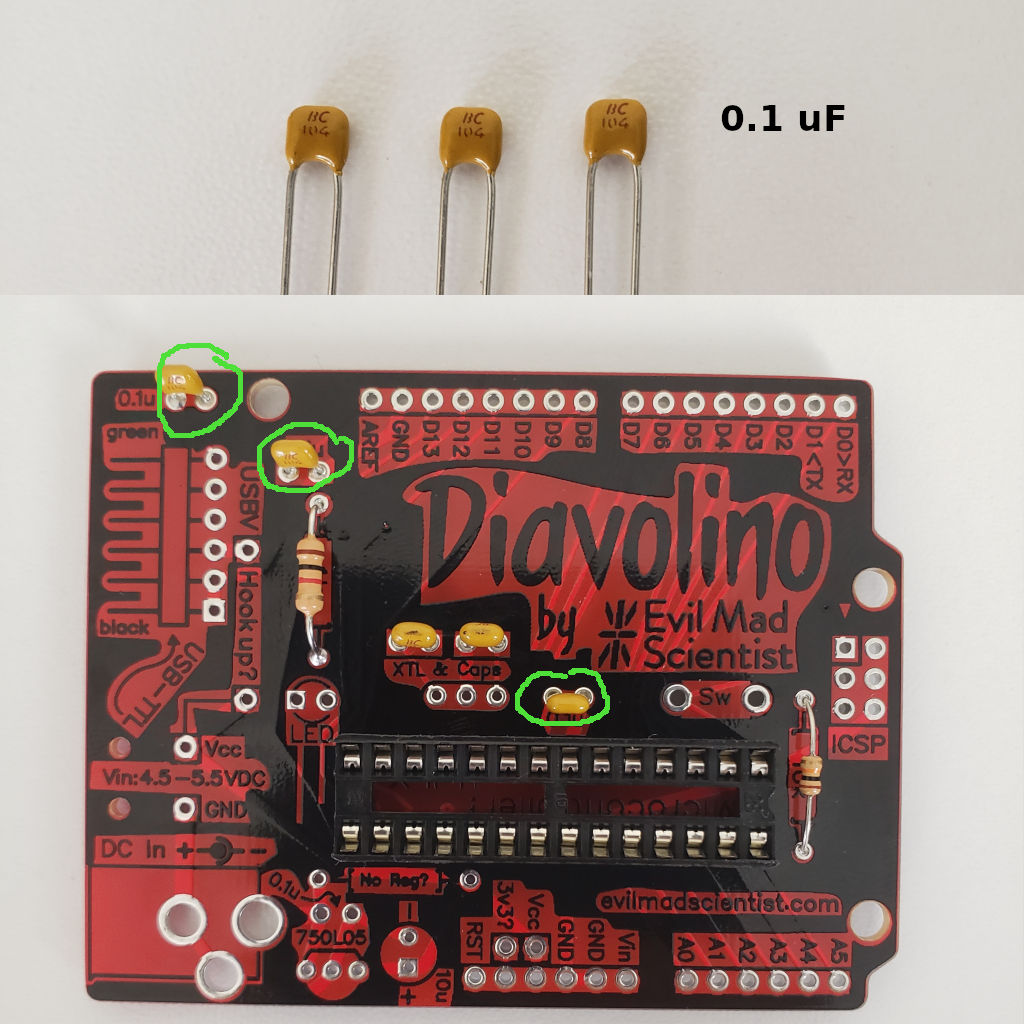
Then 0.1 uF capacitors. There are 3 of these capacitors in the kit.
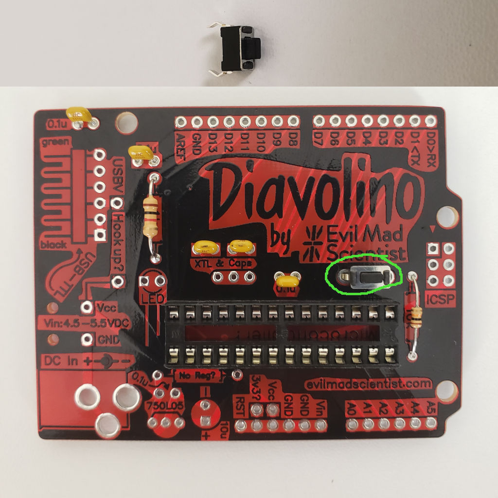
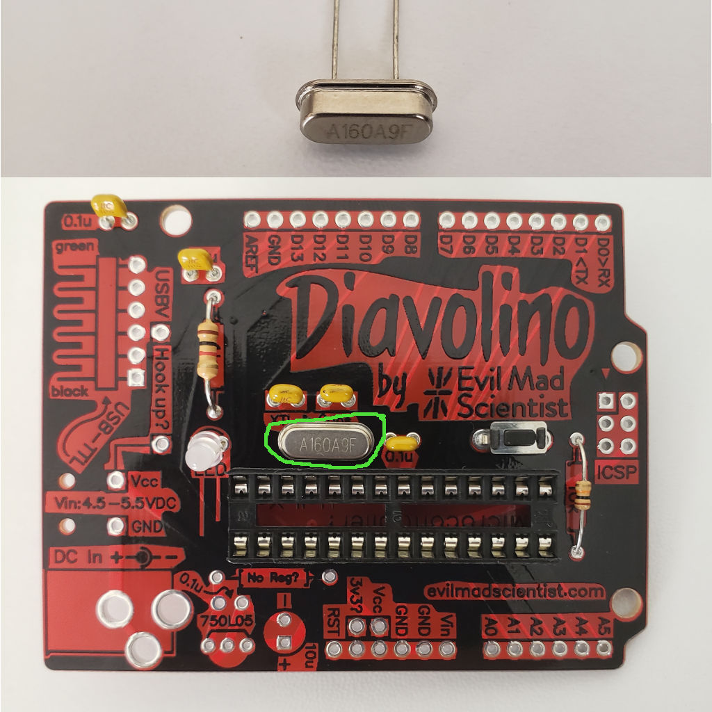
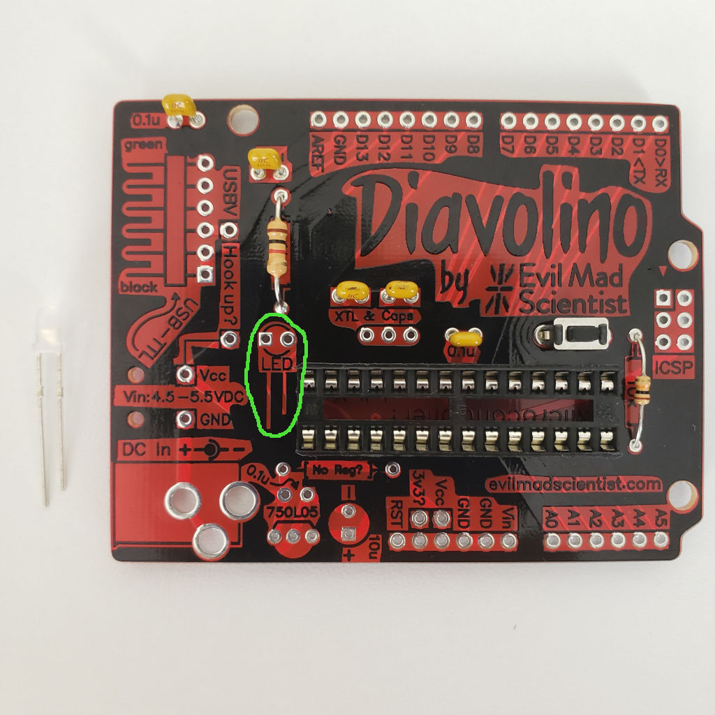
Now we can solder the reset switch, the crystal oscillator, and the LED. Pay attention to the polarity of the LED, it is drawn on the PCB.
Now we can solder optional jumpers. There are 3 jumpers in the kit. The first one called "Hook up?" will connect USB 5V power line to the board. Since we don't have external power supply, we need it. The second one called "no reg?". This one will connect the power line directly to the microcontroller without a voltage regulator. Since the voltage regulator needs to be purchased separately, and I don't have one, and power from USB is regulated to 5V anyway, I will connect the jumper. But if you use an external power supply, usually 9V, you need to solder the regulator. And the third one is the 3.3 V pin. We don't need that.
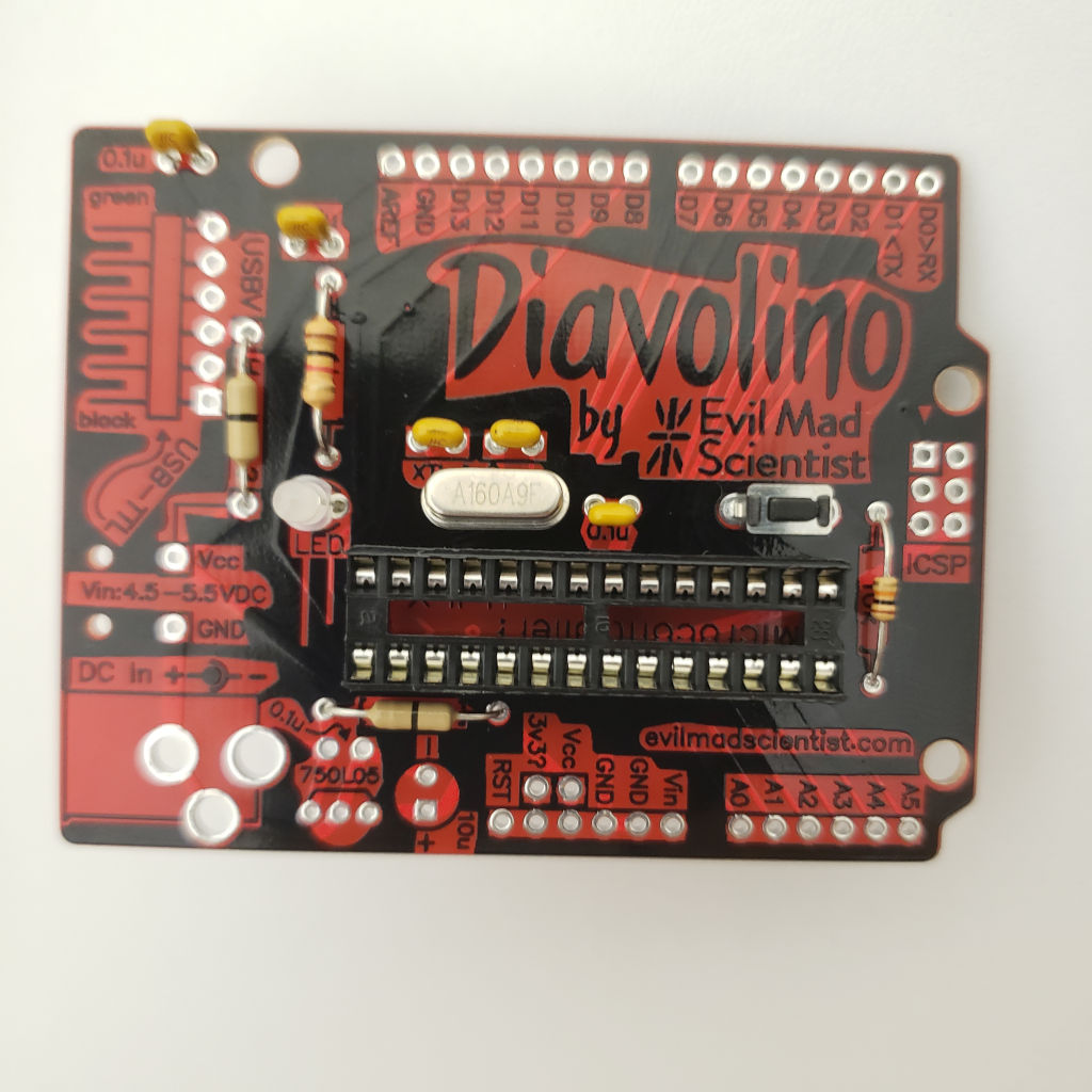
And the jumpers are in place. Your composition might be different.

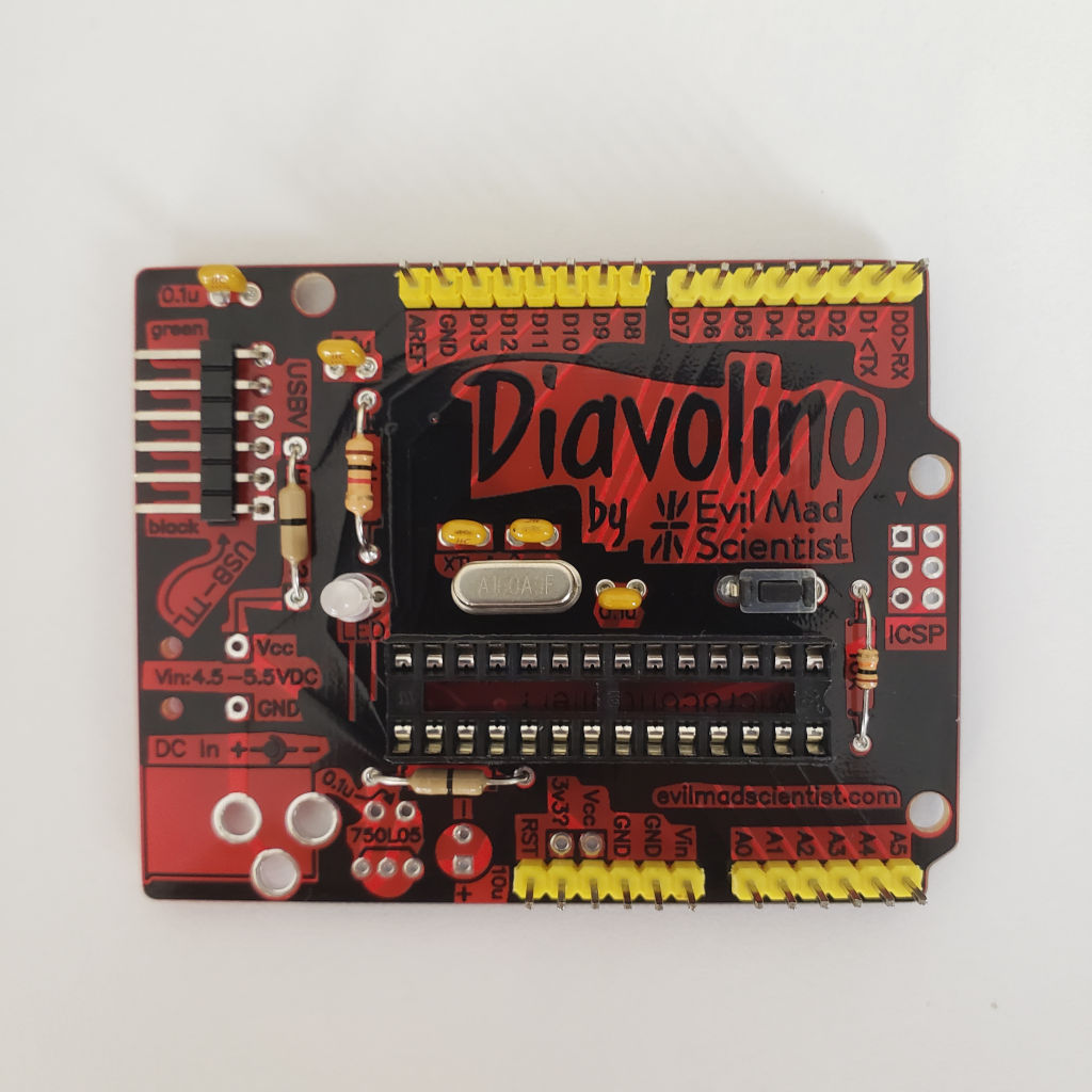
Now the pin headers.

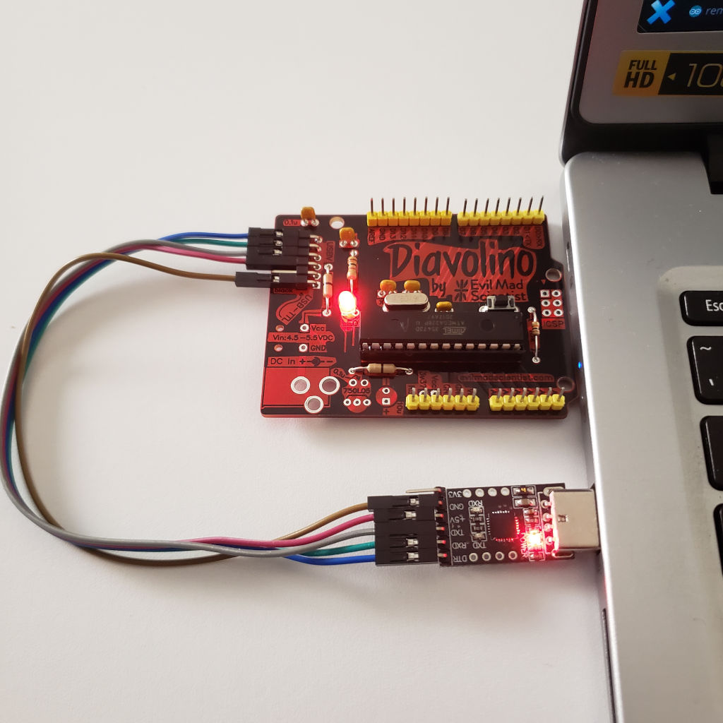
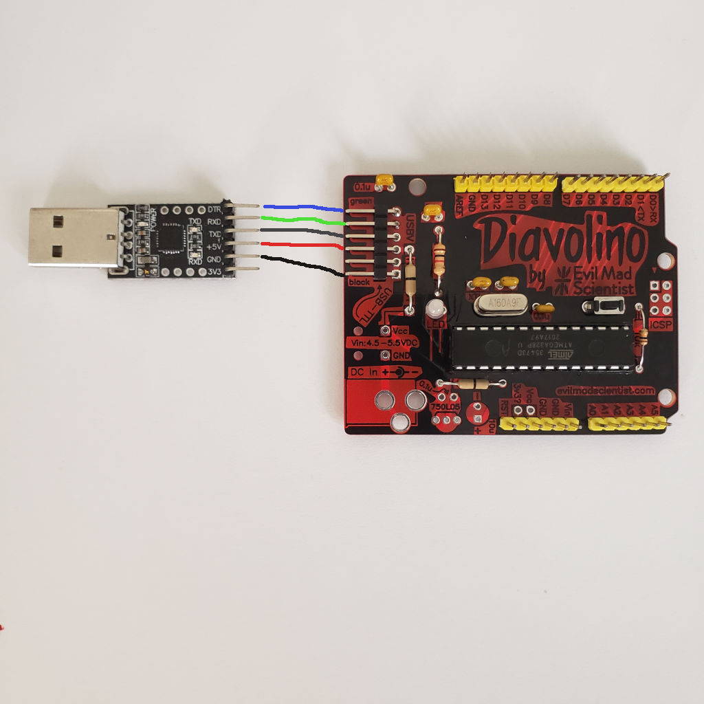
Now we need USB-TTL to connect to PC. The board is labeled with colors for connecting the FTDI USB-TTL cable. Which I don't have. The cheap USB stick from eBay connects this way.
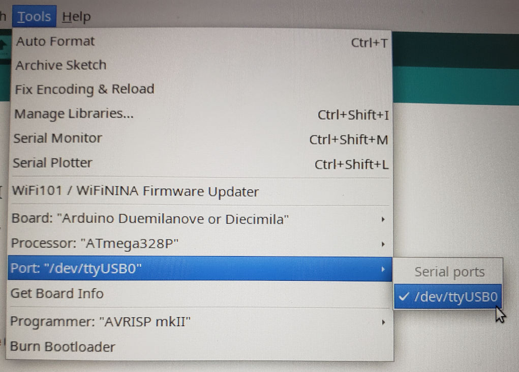
In the Arduino IDE you need to select board as "Arduino Duemilanove or Diecimila" and the port.

For the test we can use simple LED blinking script. The LED is on 13 pin.
int ledPin = 13;

void setup() {
  pinMode(ledPin, OUTPUT);
}


void loop() {
  digitalWrite(ledPin, HIGH);
  delay(1000);
  digitalWrite(ledPin, LOW);
  delay(1000);
}
And it should work and blink with red.
