DIY 3D LED Flashing Christmas Tree Circuit Kit Glitter Electronic Learning Set
Instructions for assembly: "DIY 3D LED Flashing Christmas Tree Circuit Kit Glitter Electronic Learning Set" That's how it called on eBay.

This DIY Kit you can buy on eBay cheap. It would be interesting to assemble yourself, and it would be a nice decoration for the desk and would add Xmas mood.
It came pretty fast. Inside the package:
- Two PCBs - parts of the Xmas tree;
- The base PCB;
- The battery box and a bag with electronic components.

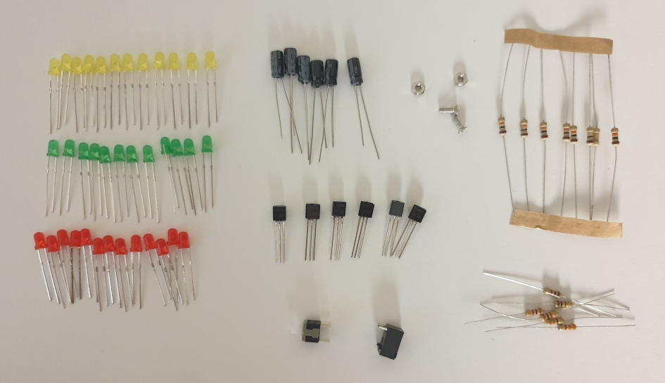
Unfortunately, It came without any instruction. And nothing is on the eBay item page. But don't worry, we will figure this out.
Let's start with LEDs. On the board, they are as D1, D2 ... D19
The longer leg is the positive side of LEDs.
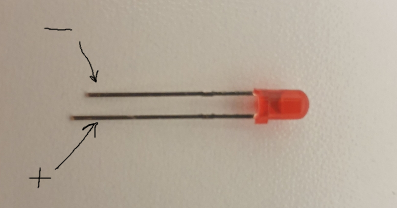
And the square pads on the PCB indicate the positive side of LEDs.
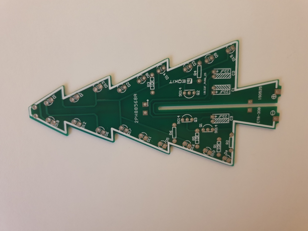
We have 3 colors of LEDs. And the schematic has 3 channels for LEDs. But I decided to mix colors. It was a mistake. Why? The reason is described below.
And the board after soldering the LEDs.
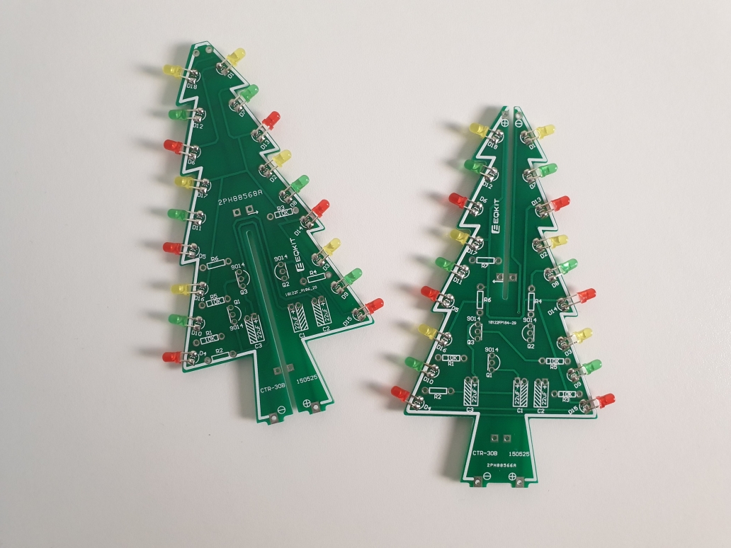
Using a 3V battery, we can test our LEDs.
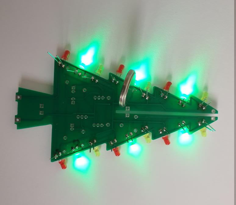
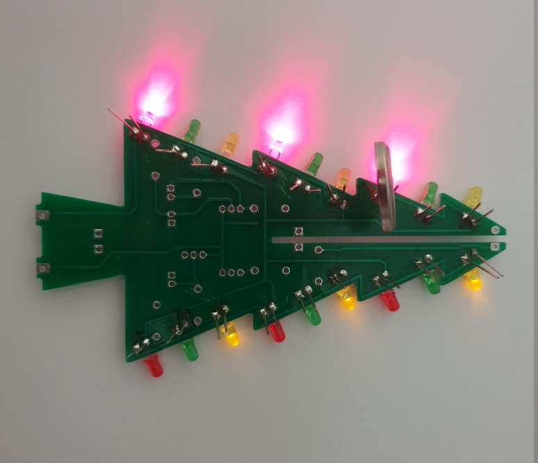
And we have a surprise here. The yellow LEDs are dim compare to others...
Let's talk about resistors. On the PCB we can see labels only for 10K resistors. It was intentional.
Here is the schematic.
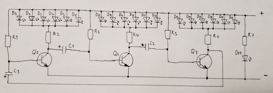
In my case, the resistors were soldered this way.

As you can see resistors R2, R4, R6 are used to connect LEDs. We can control LED brightness by changing the resistors. The less value, the more brightness. Because our LEDs mixed, the values were improvised. But You can select resistors according to your situation.
The board with resistors.
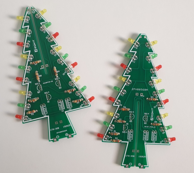
The next are transistors, shouldn't be a problem.
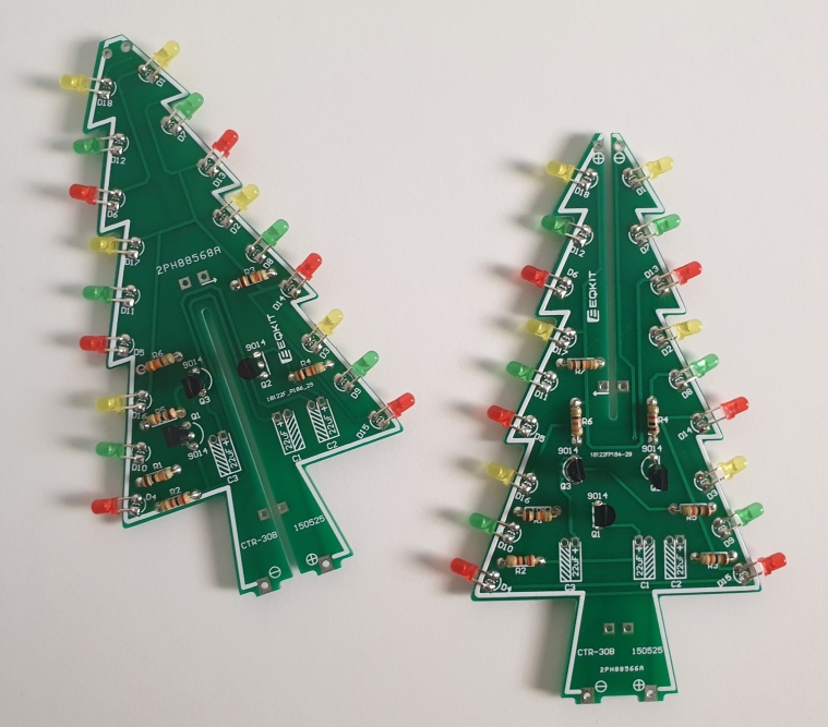
Now the capacitors. Pay attention that they have polarity. Just like the LED, the longer leg is for the positive side of the capacitor. And the square pads on the PCB are positive. Also, capacitors have a minus label for negative.
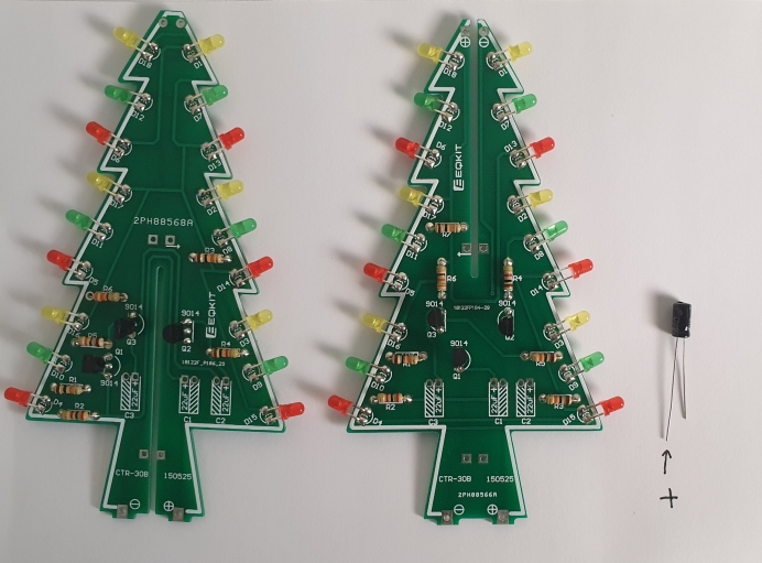
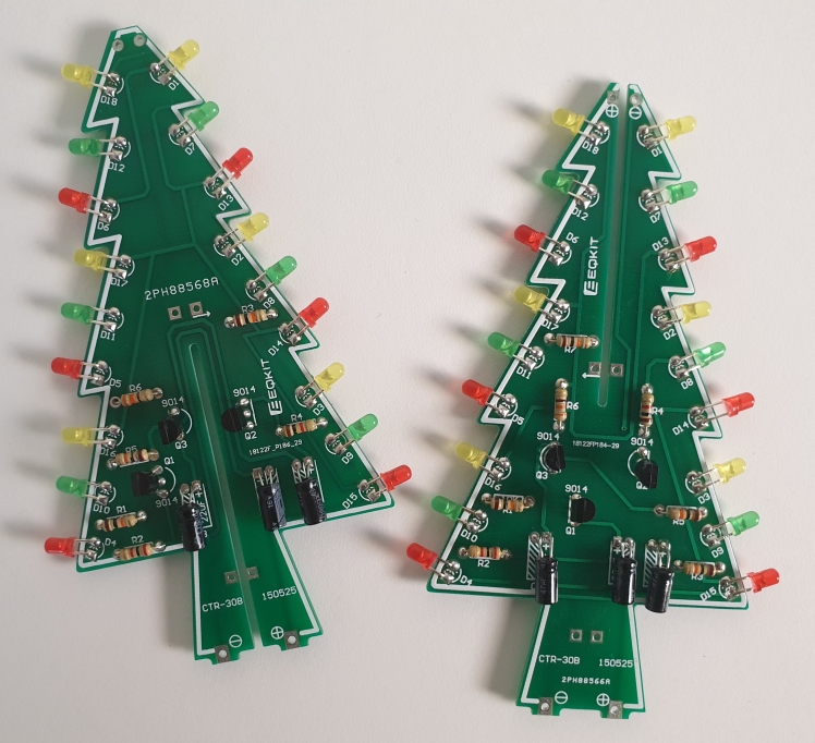
And after soldering.
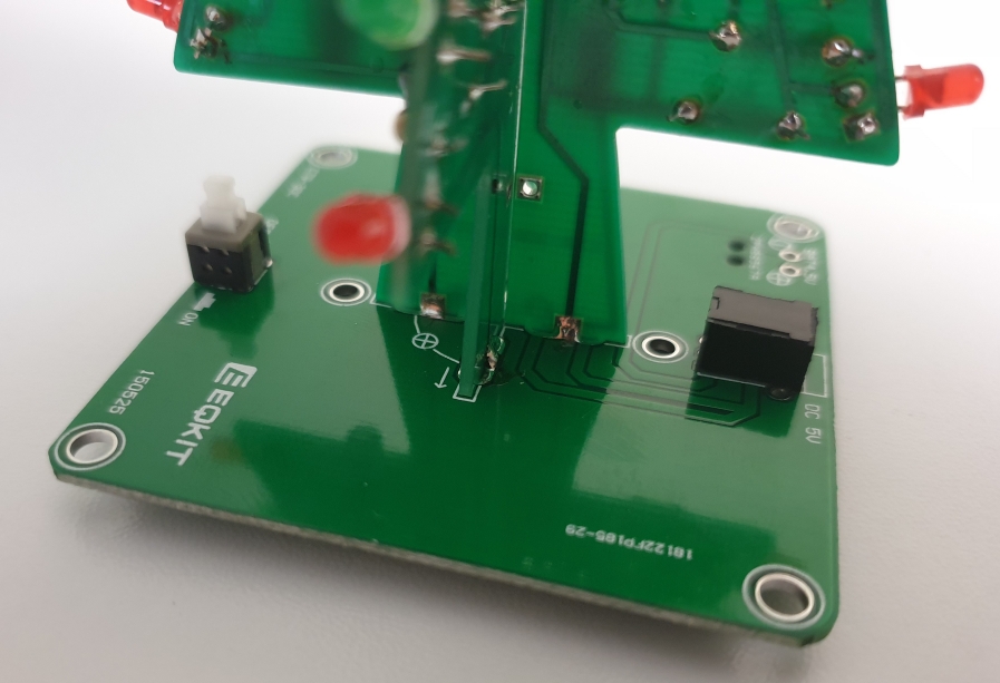
Next, we solder the power input and the power switch.
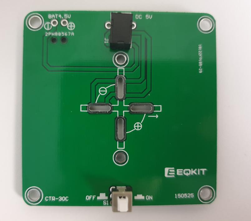
And we solder the tree to its base.
Using a USB cable we can test the Xmas tree.
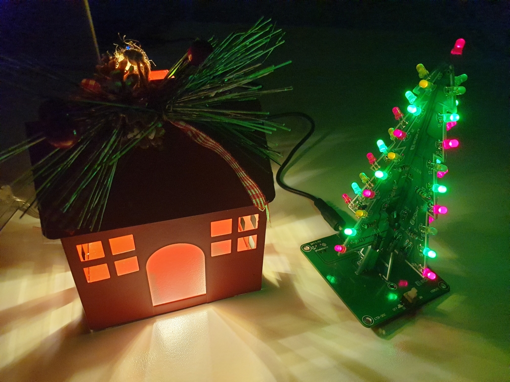
Everything is working. Now let's connect the battery box.
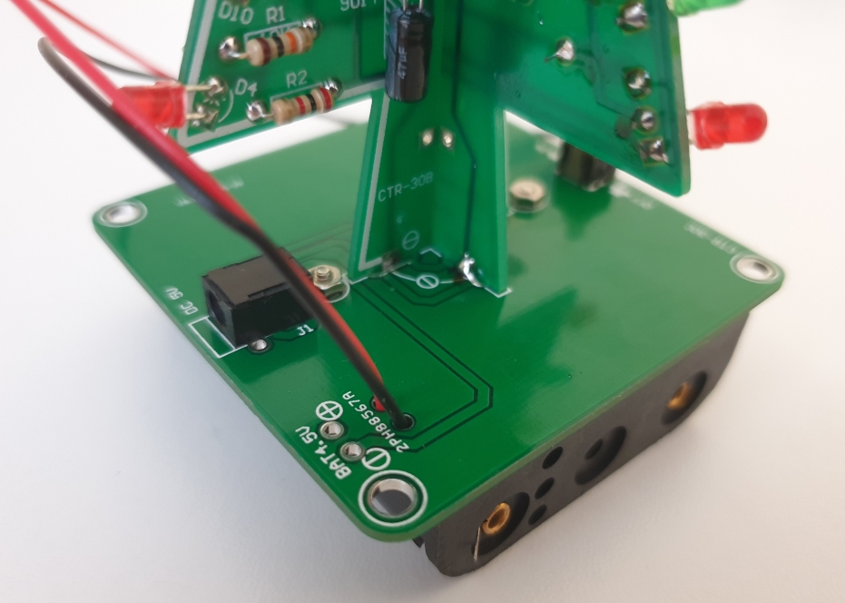
The red wire is positive and the black wire is negative.
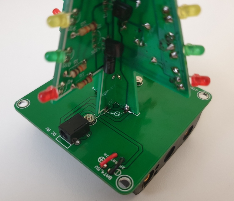
And it is ready. The last red LED goes on top of the tree.